
SMART-INTERFACE allows the SMART-1 detector technology to be used with virtually any MCA — even analog.
SMART-INTERFACE provides communications between the ORTEC SMART-1 detector and an analog amplifier with any MCA or a Digital Signal Processor that cannot directly connect to the SMART-1. Easy to use software is provided to access the SMART-1 detector's State-of-Health (SOH) data and control the high voltage.
The SMART-INTERFACE is supplied with one detector output signal cable, one inhibit output signal cable [for use with -PLUS or Transistor Reset Preamplifiers (TRP)], one preamplifier power cable for an ORTEC preamplifier power supply, one preamplifier power cable to connect to another manufacturer’s preamplifier power supply, a USB extension cable for connection to a PC and software to control the high voltage and display the detector SOH data.
SMART-INTERFACE Software
To start the SMART-INTERFACE software, click the Window’s Start button, then "ORTEC SMART-INTERFACE." Note, the software is initially minimized to the system tray. To terminate the SMART-INTERFACE software, right click the SMART-INTERFACE icon and click "Shut Down."
To see the SMART-INTERFACE dialogue box, click the SMART-INTERFACE icon in the system tray.
SMART-INTERFACE Dialogue Box
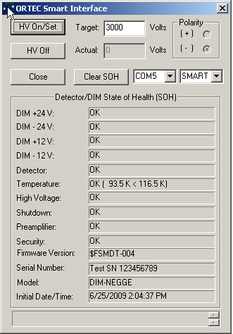
| HV On/Set |
Turns on the bias voltage to the detector and sets the HV to the target voltage. The user enters the target volts in the "Target" box. |
| Actual |
Displays the voltage applied to the detector. |
| HV Off |
Turns off bias voltage to the detector. |
| Close |
Closes the dialogue box for the SMART-INTERFACE software. Note, this does not cease operations for the SMART-INTERFACE software. |
| Clear SOH |
Clears the data from the Detector/DIM State-of-Health (SOH) chart and resets the Initial Date/Time to the current date and time. |
| Drop-Down Menu (Left) |
Selects the COM port that will be used to control the SMART-INTERFACE. |
| Drop-Down Menu (Right) |
Indicates the bias shutdown logic that is being used. This should always be set to SMART for use with a SMART-1 detector. |
SMART-INTERFACE Controls Menu
Access the SMART-INTERFACE controls menu by clicking on the upper left corner of the SMART-INTERFACE dialogue box. A drop-down menu will appear.
SMART-INTERFACE Controls
| Move |
Moves the dialogue box. |
Close (ALT+F4)
|
Closes the dialogue box
|
Set Recommended HV
|
Allows the user to enter a value for the bias (normally the recommended value from the SMART-1 detector QAD sheet).
|
Get Recommended HV
|
Acquires the value entered by the user in the Set Recommended HV step and applies this value to the "Target" box of the SMART-INTERFACE dialogue box.
|
DIM Authentication Code
|
Allows the user to change or delete the authentication code.
|
User Password
|
Opens the Manage User Password dialogue box and allows setting or deleting password protection of the HV On/Off function and provides a means of changing the password. Note, the default password is "ORTEC".
Setting the HV On/Off is password protected by default. If the "HV On/Off without Password" box is not checked in the Manage User Password dialogue box, the HV On/Off Password dialogue box will appear.
|
SMART-INTERFACE Specifications
| Preamplifier Power |
9-pin D connector provides ±12 V and ±24 V power to the preamplifier and high voltage supply. Two 12 ft (3.6 m) preamplifier power cables are provided, one for ORTEC connections and one for another manufacturer. |
Signal Output
|
Supplies the voltage pulse from the preamplifier suitable for input to a spectroscopy shaping amplifier or a Digital Signal Processor. 100-Ω impedance. A 12 ft (3.6 m) BNC cable is provided.
|
Inhibit Output
|
A logic signal is provided during the reset time from a -Plus type (Transistor Reset) preamplifier. 1 kΩ impedance. A 12 ft (3.6 m) BNC cable is provided.
|
USB Interface
|
Converts the RS232 interface to USB and provides a USB connection to a PC. Interface circuit is powered by the USB. A 10 ft (3 m) USB extension cable is provided.
|
Weight
|
Net 2 lbs. (0.9 kg) Shipping 3 lbs. (1.4 kg)
|